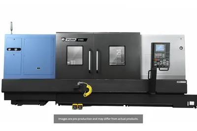
Johnford HT-80-2S
Key Specifications
Max Spindle
Rapid Traverse
Spindle Power
swing over bed
swing over cross slide
distance between centers
How much does the Johnford HT-80-2S cost?
Price estimate
We do not have a price for the Johnford HT-80-2S that we can stand behind, so we show no number. Configuration, options and installation move the final price a long way: a quote is the reliable figure.
Overview
Two metres of travel and a second spindle at the far end: the Johnford HT-80-2S has 2,000 mm (78.7 in) between centers, a 2,000 mm (78.7 in) Z stroke and a sub-spindle where a tailstock would normally sit.
This is the first HT size on which the Z and W axes get larger drives. Their servo motors are 7 kW, against 4 kW on the HT-60-2S, while the X axis stays at 4 kW. The carriage and the sub-spindle are being moved over a longer, heavier bed, and the machine weighs 20,500 kg (45,100 lb) with spindle A.
Swing over the bed is Ø710 mm (28 in), over the cross slide Ø600 mm (23.6 in). The main spindle comes in the five HT variants, and on a bed this long the large bores are the likely choice: C passes Ø139 mm (5.5 in) bar at 1,200 rpm, D passes Ø165 mm (6.5 in) at 1,000 rpm, E passes Ø204 mm (8 in) at 750 rpm, all with 30 / 37 kW (40.2 / 49.6 hp) and four automatic speed steps.
The sub-spindle is listed with Ø91 mm (3.6 in) bar capacity as standard and Ø95 mm (3.7 in) or Ø116 mm (4.6 in) as options. A single 12-station turret does the cutting at both ends, so the machine suits long parts made in sequence, not two operations running at once.
Full Specifications
| Parameter | Value |
|---|---|
| Swing Over Bed | Ø710 mm (Ø28 in) |
| Swing Over Cross Slide | Ø600 mm (Ø23.6 in) |
| Distance Between Centers | 2,000 mm (78.7 in) |
| Chuck Size | A: Ø315 mm (Ø12 in) / B: Ø381 mm (Ø15 in) / C, D: Ø510 mm (Ø20 in) / E: Ø610 mm (Ø24 in) |
| Chuck Size Optional | A: Ø381 mm (Ø15 in) / B: Ø450 mm (Ø18 in) / C, D: Ø610 mm (Ø24 in) |
| Bar Capacity | A: Ø91 mm (Ø3.6 in) / B: Ø116 mm (Ø4.6 in) / C: Ø139 mm (Ø5.5 in) / D: Ø165 mm (Ø6.5 in) / E: Ø204 mm (Ø8 in) |
| Bar Capacity Optional | A: Ø95 mm (Ø3.7 in) |
| Spindle Nose | A: A2-8 / B: A2-11 / C: A2-12 / D, E: A2-15 |
| Spindle Bore | A: Ø115 mm (Ø4.5 in) / B: Ø132.5 mm (Ø5.2 in) / C: Ø152 mm (Ø6 in) / D: Ø185 mm (Ø7.3 in), Geared head Ø176 mm (Ø6.9 in) / E: Ø236 mm (Ø9.3 in) |
| Spindle Transmission | A, B: Auto Hi-Lo / C, D, E: Auto 4-steps |
| Spindle Transmission Optional | B: Auto 4-steps |
| Max Spindle Speed | A: 3,000 rpm for 12 in chuck, 2,000 rpm for 15 in chuck / B: 2,000 rpm for Hi-Lo / C: 1,200 rpm / D: 1,000 rpm / E: 750 rpm |
| Spindle Speed Optional | B: 2,000 rpm for Auto 4-steps |
| Spindle Motor Power | A, B: 22 / 26 kW (29.5 / 34.9 hp); C, D, E: 30 / 37 kW (40.2 / 49.6 hp) |
| Spindle Power Optional | B: 30 / 37 kW (40.2 / 49.6 hp); C, D, E: 37 / 45 kW (49.6 / 60.3 hp) |
| Spindle Bearing Diameter | A: Ø160 mm (Ø6.3 in) / B: Ø180 mm (Ø7 in) / C: Ø200 mm (Ø7.9 in) / D: Ø240 mm (Ø9.4 in) / E: Ø280 mm (Ø11 in) |
| Sub Spindle Chuck Size | A: Ø315 mm (Ø12 in) / B, C, D, E: Ø381 mm (Ø15 in) |
| Sub Spindle Chuck Size Optional | A: Ø381 mm (Ø15 in) |
| Sub Spindle Bar Capacity | Ø91 mm (Ø3.6 in) (Std.) / Ø95 mm (Ø3.7 in) (Opt.) / Ø116 mm (Ø4.6 in) |
| Sub Spindle Nose | A2-8 (Std.) / A2-11 (Opt.) |
| Sub Spindle Bore | Ø115 mm (Ø4.5 in) (Std.) / Ø132.5 mm (Ø5.2 in) (Opt. for A2-11) |
| Sub Spindle Speed | A: 3,000 rpm for 12 in chuck, 2,000 rpm for 15 in chuck / B: 2,000 rpm / C: 1,500 rpm / D: 1,000 rpm / E: 750 rpm |
| Sub Spindle Power | A: 9 / 11 kW (12.1 / 14.8 hp); B: 11 / 15 kW (14.8 / 20.1 hp); C, D, E: 15 / 18.5 kW (20.1 / 24.8 hp) |
| Sub Spindle Bearing Diameter | Ø160 mm (Ø6.3 in) (Std.) / Ø180 mm (Ø7.1 in) (Opt.) |
| Turret Stations | 12 |
| X Axis Travel | 320 mm (12.6 in) |
| Z Axis Travel | 2,000 mm (78.7 in) |
| Rapid Traverse Rate | X: 12 m/min (472 ipm); Z: 15 m/min (591 ipm); W: 10 m/min (394 ipm) |
| Servo Motor X | 4 kW |
| Servo Motor Z1 Z2 | 7 kW |
| Servo Motor W | 7 kW |
| Bed Inclination | 45° |
| Machine Weight | A: 20,500 kg (45,100 lb) / B: 20,550 kg (45,210 lb) / C: 20,600 kg (45,320 lb) / D: 20,650 kg (45,430 lb) / E: 20,700 kg (45,540 lb) |
| Machine Dimensions | 6,000 x 3,470 x 2,840 mm (236.2 x 136.6 x 111.8 in) |
Specifications sourced from johnford.com.tw — verified 2026-10-04
Strengths & Limitations
Strengths
- 2,000 mm (78.7 in) of Z travel with sub-spindle transfer
- 7 kW servo motors on Z1/Z2 and W
- Bores up to Ø236 mm (9.3 in) with spindle variant E
- Optional sub-spindle bar capacity of Ø116 mm (4.6 in)
- Ø600 mm (23.6 in) swing over the cross slide
Limitations
- Swing over the bed is Ø710 mm (28 in), less than the Ø750 mm (29.5 in) of the HT-40-2S
- One turret only; the HT-80-2SD adds a second
- 6,000 mm (236.2 in) long and 20,500 kg (45,100 lb) or more
- Live tool turret, C-axis and Y axis are options
Best For
Frequently Asked Questions
01
Against the HT-60-2S, distance between centers goes from 1,500 mm (59 in) to 2,000 mm (78.7 in), the Z1/Z2 and W servo motors from 4 kW to 7 kW, and swing over the bed from Ø730 mm (28.7 in) to Ø710 mm (28 in). Length grows to 6,000 mm (236.2 in).
02
20,500 kg (45,100 lb) with spindle variant A, rising in steps to 20,700 kg (45,540 lb) with variant E. The footprint is 6,000 x 3,470 mm (236.2 x 136.6 in) and the height 2,840 mm (111.8 in).
03
Ø91 mm (3.6 in) as standard. The table also lists Ø95 mm (3.7 in) and Ø116 mm (4.6 in) as options, with a Ø132.5 mm (5.2 in) bore for the optional A2-11 nose.
04
The standard turret is a 12-position direct-mount non-driven turret with one set of turning tool holders. A live tool 12-position turret in BMT or VDI is optional, as are the C-axis and a Y axis on the upper turret.
More from Johnford
Other CNC Lathes / Turning Centers
TRAK TRL 1845RX
Campro CPL-3512
Mazak MEGA TURN 600M
Tormach 15LX
Starrag Dorries VT Series