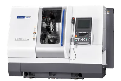
Johnford HT-60-2SD
Key Specifications
Max Spindle
Rapid Traverse
Spindle Power
swing over bed
swing over cross slide
distance between centers
How much does the Johnford HT-60-2SD cost?
Price estimate
We do not have a price for the Johnford HT-60-2SD that we can stand behind, so we show no number. Configuration, options and installation move the final price a long way: a quote is the reliable figure.
Overview
The Johnford HT-60-2SD stretches the twin-turret, twin-spindle layout to 1,500 mm (59 in) between centers, and both Z axes travel that full distance.
With that much bed between two spindles, the machine can be used in two quite different ways. For chuck parts, the spindles work as separate stations with a turret each and a transfer in between. For shafts and tubes, the two spindles can grip the same workpiece at both ends, which drives it from both sides and leaves the middle open to the turrets. The second use is where the choice of sub-spindle matters: the standard unit has an A2-8 nose and a Ø115 mm (4.5 in) bore, the optional one A2-11 and Ø132.5 mm (5.2 in).
Main spindle variants A to E cover chucks from Ø315 mm (12 in) to Ø610 mm (24 in). Sub-spindle motors scale with them: 9 / 11 kW (12.1 / 14.8 hp) alongside A, 11 / 15 kW (14.8 / 20.1 hp) alongside B, and 15 / 18.5 kW (20.1 / 24.8 hp) alongside C, D and E, where the sub-spindle also gets an Auto Hi-Lo transmission.
Swing over the bed is Ø730 mm (28.7 in). The weight is 20,000 kg (44,000 lb) with spindle A, more than the tailstock version, the HT-60-2D, at 19,000 kg (41,800 lb).
Full Specifications
| Parameter | Value |
|---|---|
| Swing Over Bed | Ø730 mm (Ø28.7 in) |
| Swing Over Cross Slide | Ø600 mm (Ø23.6 in) |
| Distance Between Centers | 1,500 mm (59 in) |
| Chuck Size | A: Ø315 mm (Ø12 in) / B: Ø381 mm (Ø15 in) / C, D: Ø510 mm (Ø20 in) / E: Ø610 mm (Ø24 in) |
| Chuck Size Optional | A: Ø381 mm (Ø15 in) / B: Ø450 mm (Ø18 in) / C, D: Ø610 mm (Ø24 in) |
| Bar Capacity | A: Ø91 mm (Ø3.6 in) / B: Ø116 mm (Ø4.6 in) / C: Ø139 mm (Ø5.5 in) / D: Ø165 mm (Ø6.5 in) / E: Ø204 mm (Ø8 in) |
| Bar Capacity Optional | A: Ø95 mm (Ø3.7 in) |
| Spindle Nose | A: A2-8 / B: A2-11 / C, D, E: A2-15 |
| Spindle Bore | A: Ø115 mm (Ø4.5 in) / B: Ø132.5 mm (Ø5.2 in) / C: Ø152 mm (Ø6 in) / D: Ø185 mm (Ø7.3 in), Geared head Ø176 mm (Ø6.9 in) / E: Ø236 mm (Ø9.3 in) |
| Spindle Transmission | A, B: Auto Hi-Lo / C, D, E: Auto 4-steps |
| Spindle Transmission Optional | B: Auto 4-steps |
| Max Spindle Speed | A: 3,000 rpm for 12 in chuck, 2,000 rpm for 15 in chuck / B: 2,000 rpm for Hi-Lo / C: 1,200 rpm / D: 1,000 rpm / E: 750 rpm |
| Spindle Speed Optional | B: 2,000 rpm for Auto 4-steps |
| Spindle Motor Power | A, B: 22 / 26 kW (29.5 / 34.9 hp); C, D, E: 30 / 37 kW (40.2 / 49.6 hp) |
| Spindle Power Optional | B: 30 / 37 kW (40.2 / 49.6 hp); C, D, E: 37 / 45 kW (49.6 / 60.3 hp) |
| Spindle Bearing Diameter | A: Ø160 mm (Ø6.3 in) / B: Ø180 mm (Ø7 in) / C: Ø200 mm (Ø7.9 in) / D: Ø240 mm (Ø9.4 in) / E: Ø280 mm (Ø11 in) |
| Sub Spindle Chuck Size | A: Ø315 mm (Ø12 in) / B, C, D, E: Ø381 mm (Ø15 in) |
| Sub Spindle Chuck Size Optional | A: Ø381 mm (Ø15 in) |
| Sub Spindle Bar Capacity | Ø91 mm (Ø3.6 in) (Std.) / Ø95 mm (Ø3.7 in) (Opt.) / Ø116 mm (Ø4.6 in) (Opt. for A2-11) |
| Sub Spindle Nose | A2-8 (Std.) / A2-11 (Opt.) |
| Sub Spindle Bore | Ø115 mm (Ø4.5 in) (Std.) / Ø132.5 mm (Ø5.2 in) (Opt.) |
| Sub Spindle Speed | A: 3,000 rpm for 12 in chuck, 2,000 rpm for 15 in chuck / B: 2,000 rpm / C: 1,500 rpm / D: 1,000 rpm / E: 750 rpm |
| Sub Spindle Power | A: 9 / 11 kW (12.1 / 14.8 hp); B: 11 / 15 kW (14.8 / 20.1 hp); C, D, E: 15 / 18.5 kW (20.1 / 24.8 hp) |
| Sub Spindle Bearing Diameter | Ø160 mm (Ø6.3 in) (Std.) / Ø180 mm (Ø7.1 in) (Opt.) |
| Turret Stations | 12 / 12 |
| X Axis Travel | 320 / 320 mm (12.6 / 12.6 in) |
| Z Axis Travel | 1,500 mm (59 in) |
| Rapid Traverse Rate | X: 12 m/min (472 ipm); Z: 15 m/min (591 ipm); W: 10 m/min (394 ipm) |
| Servo Motor X1 X2 | 4 kW |
| Servo Motor Z1 Z2 | 4 kW |
| Servo Motor W | 4 kW |
| Bed Inclination | 45° |
| Machine Weight | A: 20,000 kg (44,000 lb) / B: 20,050 kg (44,110 lb) / C: 20,100 kg (44,220 lb) / D: 20,150 kg (44,330 lb) / E: 20,200 kg (44,440 lb) |
| Machine Dimensions | 5,600 x 3,470 x 2,840 mm (220.5 x 136.6 x 111.8 in) |
Specifications sourced from johnford.com.tw — verified 2026-10-04
Strengths & Limitations
Strengths
- Both turrets travel the full 1,500 mm (59 in) on Z
- Sub-spindle motor up to 15 / 18.5 kW (20.1 / 24.8 hp) with an Auto Hi-Lo transmission
- Main bar capacity from Ø91 mm (3.6 in) to Ø204 mm (8 in)
- Two 12-station turrets under dual-path control
- Ø600 mm (23.6 in) swing over the cross slide
Limitations
- Sub-spindle bore is Ø115 mm (4.5 in) as standard
- Weighs 20,000 kg (44,000 lb) or more
- No tailstock for center support
- Rapid traverse is 12 m/min on X, 15 m/min on Z and 10 m/min on W
Best For
Frequently Asked Questions
01
Yes. The table gives one figure for Z1/Z2, 1,500 mm (59 in), and 320 / 320 mm (12.6 / 12.6 in) for X1/X2. On the tailstock version, the HT-60-2D, the second Z axis is shorter at 1,260 mm (49.6 in).
02
It follows the main spindle variant: 9 / 11 kW (12.1 / 14.8 hp) with A, 11 / 15 kW (14.8 / 20.1 hp) with B and 15 / 18.5 kW (20.1 / 24.8 hp) with C, D or E. With A the sub-spindle is one step; with the others it has an Auto Hi-Lo transmission.
03
20,000 kg (44,000 lb) with spindle A, 20,050 kg (44,110 lb) with B, 20,100 kg (44,220 lb) with C, 20,150 kg (44,330 lb) with D and 20,200 kg (44,440 lb) with E. It measures 5,600 x 3,470 x 2,840 mm (220.5 x 136.6 x 111.8 in).
04
As an option, on the upper turret only. The optional accessory list also has a live tool 12-position turret in BMT or VDI and a C-axis, either a C.S axis with angle encoder and no gearbox or a C.F axis with gearbox.
More from Johnford
Other CNC Lathes / Turning Centers
Campro CPL-30MC
Mazak MEGA TURN 500M
Starrag Dorries VC Series
DN Solutions PUMA 1000 MB