ROMI C 420
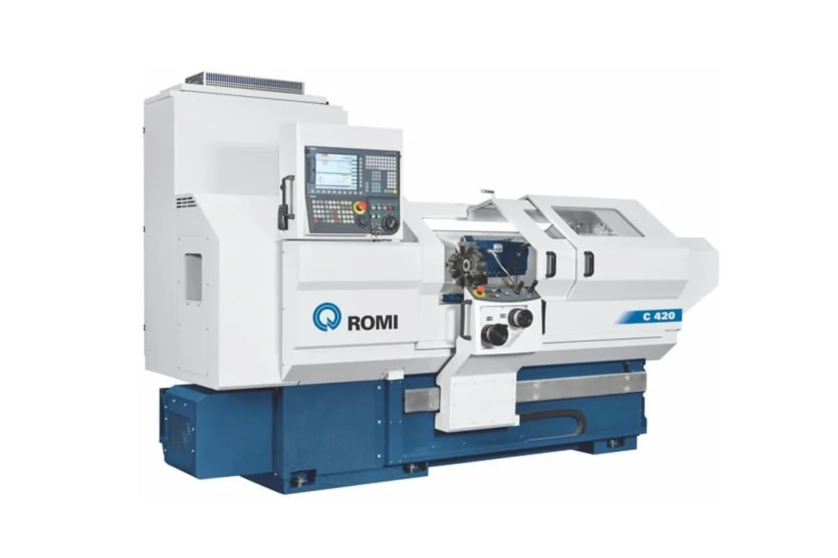
Image: romi.com, Romi
Key Specifications
Max Spindle
Spindle Power
centers height
distance between centers
swing over bed
swing over cross slide
How much does the ROMI C 420 cost?
Price estimate
We do not have a price for the ROMI C 420 that we can stand behind, so we show no number. Configuration, options and installation move the final price a long way: a quote is the reliable figure.
Overview
The ROMI C 420 is the entry model of Romi's C Series of flat-bed CNC lathes. It swings 430 mm (16.9 in) over the bed, takes 1.0 m (39 in) between centers and weighs about 2,500 kg (5,500 lbs), which makes it a lathe that fits where a manual engine lathe used to stand.
What sets the C 420 apart inside the range is how many ways it can be tooled. Romi lists gang tools for this size only, in 20 x 20 mm (0.79 x 0.79 in) shanks, next to a quick change tool holder with 2 or 3 holders, a rear tool holder and an 8-station horizontal automatic turret. All of them are options, so the tooling has to be chosen with the order. A gang plate suits short bar parts with a handful of tools. The turret suits mixed shaft work.
The headstock comes in two versions on one 12.5 hp / 9 kW motor. With the A2-5” nose the spindle runs from 4 to 4,000 rpm, has a 53 mm (2.1 in) bore and gives 110 Nm (81 lb-ft). The A2-6” nose trades speed for bore and torque: 3 to 3,000 rpm, 65 mm (2.6 in) and 140 Nm (103 lb-ft).
Mind the cross slide. Only 200 mm (7.9 in) swings over it, so the full bed swing is for face work held in the chuck. Travels are 220 mm (8.7 in) in X and 1,065 mm (42 in) in Z at 10 m/min (394 in/min). The tailstock is positioned by hand, and its quill can be manual, pneumatic or hydraulic. A Siemens Sinumerik 828D runs the machine, and the carriage has electronic handwheels for turning a part the way it is done on an engine lathe.
Full Specifications
| Parameter | Value |
|---|---|
| Centers Height | 215 mm (8.5 in) |
| Distance Between Centers | 1.0 m (39 in) |
| Swing Over Bed | 430 mm (16.9 in) |
| Swing Over Cross Slide | 200 mm (7.9 in) |
| Swing Over Saddle Wings | 400 mm (15.7 in) |
| X Axis Travel | 220 mm (8.7 in) |
| Z Axis Travel | 1,065 mm (42 in) |
| Bed Width | 305 mm (12 in) |
| Bed Height | 350 mm (13.8 in) |
| Spindle Nose | ASA A2-5” or A2-6” |
| Spindle Bore | 53 mm (2.1 in) with A2-5”; 65 mm (2.6 in) with A2-6” |
| Transmission System | Direct drive |
| Max Spindle Speed | 4 to 4,000 rpm with A2-5”; 3 to 3,000 rpm with A2-6” |
| Spindle Torque | 110 Nm (81 lb-ft) with the A2-5” headstock; 140 Nm (103 lb-ft) with the A2-6” headstock (S6 - 40% rating) |
| Rapid Traverse Z | 10 m/min (394 in/min) |
| Rapid Traverse X | 10 m/min (394 in/min) |
| Tailstock Body Positioning | Manual |
| Tailstock Quill Drive | Manual (std) / Pneumatic or Hydraulic (opt) |
| Tailstock Quill Stroke | 120 mm (4.7 in) |
| Tailstock Quill Diameter | 60 mm (2.4 in) |
| Tailstock Quill Taper | CM 4 |
| Spindle Motor Power | 12.5 hp / 9 kW (S6 - 40% rating) |
| Power Requirement | 20 kVA |
| Floor Space | 3.10 x 1.24 m (122 x 49 in) without chip conveyor |
| Machine Weight | 2,500 kg (5,500 lbs) approx. net |
| Quick Change Tool Holder | Optional, 2 or 3 holders, 25 x 25 mm (0.98 x 0.98 in) square, Ø 25 mm (0.98 in) round |
| Gang Tooling | Optional, 20 x 20 mm (0.79 x 0.79 in) square, Ø 25 mm (0.98 in) round |
| Rear Tool Holder | Optional, 20 x 20 mm (0.79 x 0.79 in) square, Ø 25 mm (0.98 in) round |
| Turret Stations | 8 (optional horizontal automatic turret, Romi tool holder fixing) |
| Turret Tool Section | 25 x 25 mm (0.98 x 0.98 in) |
| Turret Boring Bar Diameter | Ø 25 mm (0.98 in) |
| CNC Control | Siemens Sinumerik 828D |
Specifications sourced from romi.com — verified 2026-10-04
Strengths & Limitations
Strengths
- Gang tools in 20 x 20 mm (0.79 x 0.79 in) shanks are offered on this size, alongside a turret, a rear tool holder and a quick change holder
- Choice of a 4 to 4,000 rpm A2-5” spindle or an A2-6” spindle with a 65 mm (2.6 in) bore
- Floor space of 3.10 x 1.24 m (122 x 49 in) without chip conveyor, on 20 kVA
- Pneumatic or hydraulic quill drive available for the tailstock
- Electronic handwheels on the carriage for engine-lathe style work
Limitations
- Swing over the cross slide is only 200 mm (7.9 in)
- Torque peaks at 140 Nm (103 lb-ft), and that only with the slower A2-6” headstock
- Every tool holder and turret in the table is an option
- The tailstock body is moved by hand; no drag positioning is listed for this size
Best For
Frequently Asked Questions
01
Swing over the bed is 430 mm (16.9 in), over the saddle wings 400 mm (15.7 in) and over the cross slide 200 mm (7.9 in). Distance between centers is 1.0 m (39 in). The cross slide travels 220 mm (8.7 in) and the carriage 1,065 mm (42 in).
02
Two, both direct drive on a 12.5 hp / 9 kW motor (S6 - 40% rating). The A2-5” headstock covers 4 to 4,000 rpm with a 53 mm (2.1 in) hole and 110 Nm (81 lb-ft). The A2-6” headstock covers 3 to 3,000 rpm with a 65 mm (2.6 in) hole and 140 Nm (103 lb-ft).
03
The catalogue lists these as options: a quick change tool holder with 2 or 3 holders for 25 x 25 mm (0.98 x 0.98 in) tools, a rear tool holder and gang tools for 20 x 20 mm (0.79 x 0.79 in) tools, and an 8-station horizontal automatic turret for 25 x 25 mm (0.98 x 0.98 in) shanks.
04
The body is positioned manually. The quill has a manual drive as standard and a pneumatic or hydraulic drive as an option, with a maximum stroke of 120 mm (4.7 in), a diameter of 60 mm (2.4 in) and a CM 4 taper hole.
More from Romi
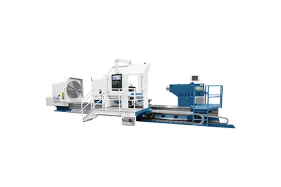
Other CNC Lathes / Turning Centers
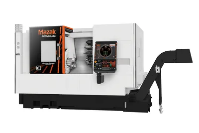
Mazak Quick Turn 450MY
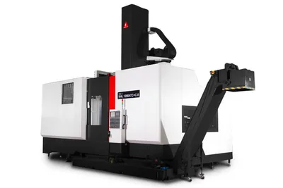
You Ji VHL2000ATC
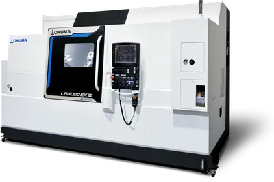
Okuma LB4000 EX III