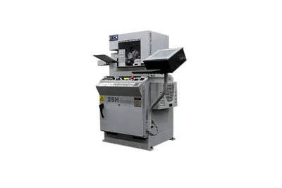
Klingelnberg P 40 Precision Measuring Center
Key Specifications
Max Workpiece ⌀
module range
horizontal measuring interval x
max moment of inertia
max workpiece weight
vertical measuring interval z
How much does the Klingelnberg P 40 Precision Measuring Center cost?
Estimated price range
Our best estimate for a cnc gear cutting machine in this class — not a quote from Klingelnberg. Configuration moves it a long way.
Overview
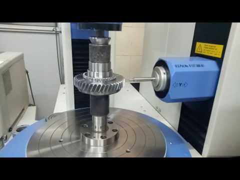
The Klingelnberg P 40 Precision Measuring Center checks cylindrical gears up to 400 mm in clamping and testing diameter between centers, in modules of 0.30 – 20 mm, with a workpiece weight of up to 300 kg. Module 0.10 mm appears in brackets in Klingelnberg's table, so treat it as outside the plain range until confirmed.
Its accuracy statement has three layers, each tied to a standard. For gear measurement the machine is classed Group A under VDI/VDE 2612 sheet 6. For length measurement the error MPE_E0 follows ISO 10360-2:2010. For the rotary axis, roundness and total axial runout follow VDI/VDE 2617 sheet 8.
The numbers depend on the room. Between 18 and 22 Celsius, MPE_E0 is 1.8 µm + L/450 mm, roundness 0.3 µm and total axial runout 1.5 µm. Between 15 and 35 Celsius the constant part of MPE_E0 stays at 1.8 µm but the length term becomes L/250 mm, roundness rises to 0.5 µm and axial runout to 1.8 µm. The difference in length error between the two bands is all in the length term, so the penalty for a warm shop grows with the length being measured. A long shaft measured over most of the Z interval pays more than a narrow gear.
That Z interval is 550 mm, with 700 mm in brackets, and the distance between centers is 50 – 800 mm, with 1,000 mm in brackets. The X axis measures over ±115 mm. Installation is undemanding for the accuracy class: 0.7 kVA including the printer, compressed air at 6 bar and 1 l/min, and a net weight of approx. 2,200 kg with standard equipment.
Full Specifications
| Parameter | Value |
|---|---|
| Module Range | (0.10), 0.30 – 20 mm |
| Horizontal Measuring Interval X | ±115 mm |
| Max Workpiece Diameter | 400 mm (clamping/testing diameter of cylindrical gears between centers) |
| Max Moment of Inertia | 5 kgm² |
| Max Workpiece Weight | 300 kg |
| Vertical Measuring Interval Z | 550 (700) mm |
| Distance Between Centers | 50 – 800 (1,000) mm |
| Machine Accuracy Gear Measurement | Group A (VDI/VDE 2612 sheet 6) |
| Mpe E0 at 18 22 C | 1.8 µm + L/450 mm (ISO 10360-2:2010) |
| Roundness at 18 22 C | 0.3 µm (Ø 100/L, VDI/VDE 2617 sheet 8) |
| Total Axial Runout at 18 22 C | 1.5 µm (VDI/VDE 2617 sheet 8) |
| Mpe E0 at 15 35 C | 1.8 µm + L/250 mm (ISO 10360-2:2010) |
| Roundness at 15 35 C | 0.5 µm (Ø 100/L, VDI/VDE 2617 sheet 8) |
| Total Axial Runout at 15 35 C | 1.8 µm (VDI/VDE 2617 sheet 8) |
| Rated Power | 0.7 kVA (including printer) |
| Compressed Air Connection | 6 bar / 1 l/min |
| Machine Weight | 2,200 kg (net, incl. standard equipment, approx.) |
| Machine Dimensions | 2,015 x 2,505 x 2,200 (2,400) mm (L x W x H, approx.) |
Specifications sourced from klingelnberg.com — verified 2026-10-03
Strengths & Limitations
Strengths
- Group A gear measurement accuracy under VDI/VDE 2612 sheet 6
- MPE_E0 of 1.8 µm + L/450 mm between 18 and 22 Celsius (ISO 10360-2:2010)
- Still specified between 15 and 35 Celsius, at 1.8 µm + L/250 mm
- Roundness of 0.3 µm and total axial runout of 1.5 µm under VDI/VDE 2617 sheet 8 in the narrower band
- Rated power of only 0.7 kVA including the printer
Limitations
- Roundness rises from 0.3 µm to 0.5 µm and axial runout from 1.5 µm to 1.8 µm in the 15 to 35 Celsius band
- Clamping and testing diameter stops at 400 mm between centers
- Maximum moment of inertia of 5 kgm² can exclude wide parts that are under the 300 kg weight limit
- The 700 mm vertical interval and 1,000 mm between centers are bracketed figures, not the base values
Best For
Frequently Asked Questions
01
Klingelnberg classes it Group A for gear measurement (VDI/VDE 2612 sheet 6). Between 18 and 22 Celsius the length measuring error MPE_E0 is 1.8 µm + L/450 mm, roundness 0.3 µm and total axial runout 1.5 µm.
02
The table gives a second set of figures for 15 to 35 Celsius: MPE_E0 of 1.8 µm + L/250 mm, roundness of 0.5 µm and total axial runout of 1.8 µm. The machine is therefore specified for that wider band, with a larger length-dependent error than between 18 and 22 Celsius.
03
Three. Gear measurement accuracy is Group A under VDI/VDE 2612 sheet 6. The length measuring error MPE_E0 is stated to ISO 10360-2:2010. Roundness, measured as Ø 100/L, and total axial runout are stated to VDI/VDE 2617 sheet 8.
04
Cylindrical gears up to 400 mm in clamping and testing diameter between centers, up to 300 kg and up to 5 kgm² in moment of inertia. The distance between centers is 50 – 800 mm, with 1,000 mm in brackets, and the vertical measuring interval is 550 mm, with 700 mm in brackets.
Videos
Sandeep saroha

Super Hobs & Broaches Pvt. Ltd.
More from Klingelnberg
Klingelnberg G 60 Bevel Gear Grinding Machine
Klingelnberg P 40
Klingelnberg P 65
Klingelnberg P 26
Klingelnberg C 50 Bevel Gear Cutting Center
Klingelnberg C 50 Bevel Gear Cutting Machine
Other CNC Gear Cutting Machines
HNK HGG-6000
Nidec Machine Tool MSS300
EMAG CLC 500 H-FR